

Free Download Autodesk AutoCAD Mechanical 2027 with LPs & Offline Helps | 9.5 Gb
Languages Supported: English, Čeština, Português, Français, Deutsch, Italiano,
日本語, 한국어, Polski, Русский, Español, 简体中文, 繁體中文
Autodeskhas releasedAutoCAD Mechanical 2027 Toolsetis a powerful extension to standard design and 2D drafting software with specialist functionality for the manufacturing, engineering, and mechanical design sectors and companies involved in digital prototyping workflows.
What's New in AutoCAD Mechanical 2027 Toolset
Revision Updates to ANSI Standard Symbols (What's New in 2027)
The ANSI standard now supports the latest revisions of ASME Y14.5 - 2018 R(2024) for the feature control frame symbol, datum target symbol, and datum identifier symbol.
Note: AutoCAD Mechanical toolset continues to support all legacy revision. Documents created in previous releases can be opened, edited, and saved without updating to the latest standard. When saving the feature control frame symbol in the new revision to an older file format, it converts the feature control frame symbol to a block.
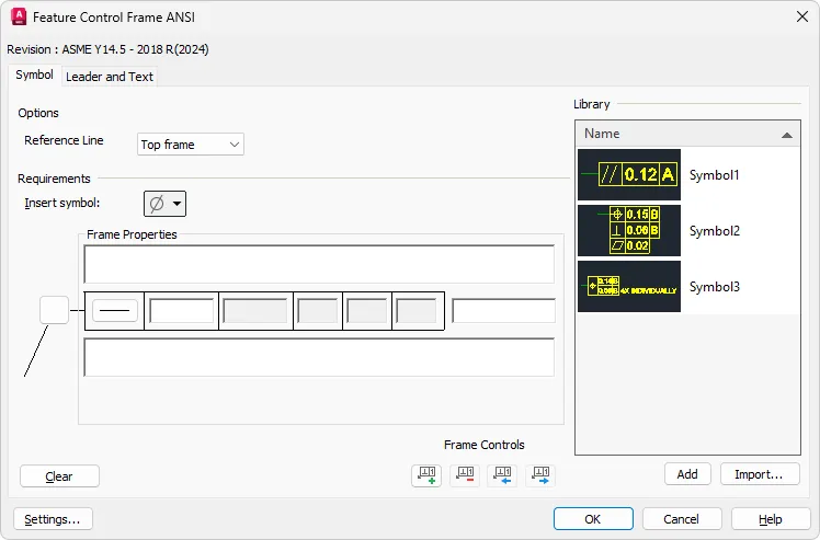
Feature Control Frame
The Feature Control Frame ANSI dialog box includes the latest standard revision, ASME Y14.5 - 2018 R(2024), providing the most up-to-date notation and requirements. The dialog box supports multi-frame functionality, allowing the addition of more frames as required, along with a field for inline notes. The Insert Symbol library has new symbols under the additional symbols category.
Close
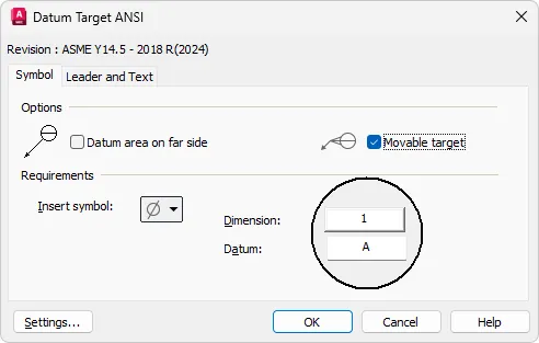
Datum Target
The Datum Target ANSI dialog box includes the latest standard revision ASME Y14.5 - 2018 R(2024). The dialog box now supports a new option to insert a movable target symbol.
Close
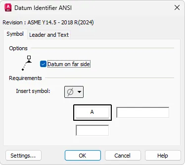
Datum Identifier
The Datum Identifier ANSI dialog box includes the latest standard revision ASME Y14.5 - 2018 R(2024). The dialog box now provides the option to insert symbols on the far side. Under Requirements, datum note, and thread note fields are provided along with the Insert symbol option.
Close
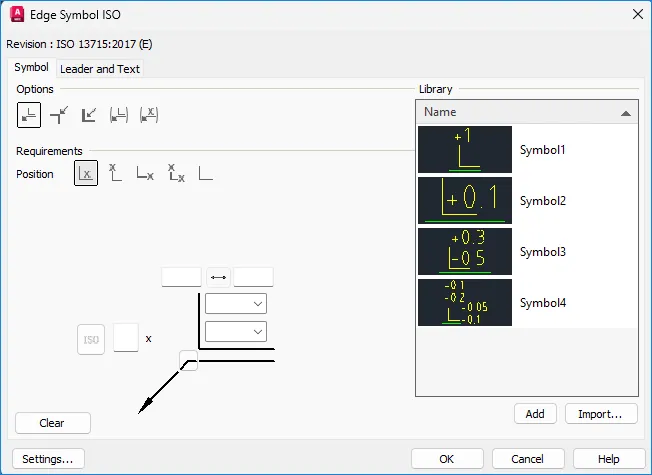
Revision Updates to ISO Standard Symbols (What's New in 2027)
The ISO standard now supports the latest revision of ISO 13715:2017 (E) for the Edge symbol. The Edge Symbol ISO dialog box provides the most up-to-date notation and requirements. The dialog box supports various options and positions to place the edge symbol in the drawing. It also offers options to define the edge quantity and indicate the limited areas of the edge.
Close
Note: The AutoCAD Mechanical toolset continues to support all legacy revisions. Documents created in previous releases can be opened, edited, and saved without updating to the latest standard. When saving the Edge symbol in the new revision to an older file format, the software converts the Edge symbol to a block.
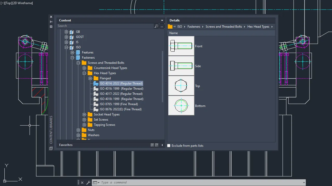
Enhanced Content Library Parts
More than 780 mechanical standard parts are updated to the latest revision in the content library of AutoCAD Mechanical 2027. These parts are available in English and all other supported languages in AutoCAD Mechanical.
The updated content includes:
- Metric ISO-Thread-Tapped Holes (Through): ISO 262: 2023 (Regular Thread)
- Thread Blind-Tapped Holes (Blind Standard Runout): ISO 262: 2023 (Regular Thread)
- Hexagon Head Bolt: ISO 4014: 2022 (Regular Thread)
- Hexagon Head Bolt: ISO 4017: 2022 (Regular Thread)
- Hexagon Nut: ISO 4032: 2023 (Regular Thread)
- Hexagon Nut: ISO 4035: 2023 (Regular Thread)

xAutodesk AutoCAD Mechanical 2027 with LPs & Offline Helps
Close
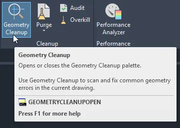
Geometry Cleanup (What's New in 2027)
Geometry Cleanup scans drawings to fix common geometry errors. Geometry Cleanup scans drawings to find common geometry errors including gaps, overshoots, undershoots, and misaligned angles. It highlights errors directly in the drawing window with visual markers. Additionally, Geometry Cleanup offers several options for each error, allowing you to choose the best fix. You can also choose to ignore suggestions and keep the geometry as designed when needed. Geometry Cleanup is fast, visual, and precise. To use Geometry Cleanup, start by opening the palette. You can do this by typing GEOMETRYCLEANUPOPEN at the Command prompt, or from the ribbon, click Manage tab > Cleanup panel > Geometry Cleanup.
Close
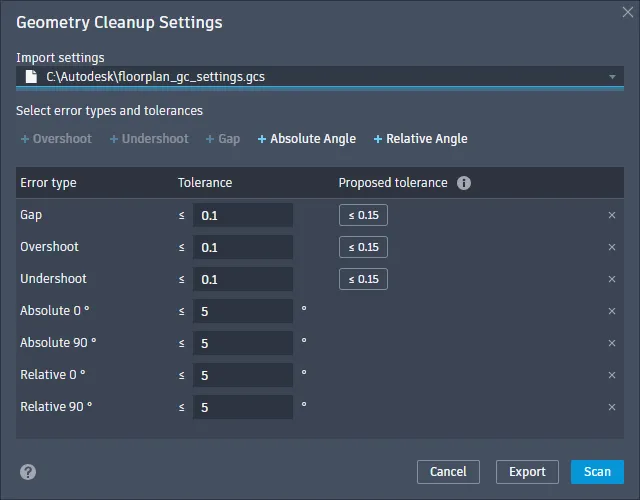
Next, select the objects you want to scan. Customize the settings by selecting the error types and setting the tolerances from the Geometry Cleanup Settings dialog box. You can also export tolerance settings and import template files for consistency across drawing or project types.
Close
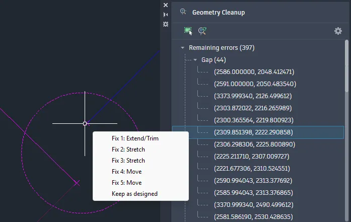
Finally, review and fix the found errors by clicking through them. Hovering over the visual marker will display fix options, and hovering over a fix option will allow you to preview the fix in real time on the canvas. Click on a fix option to apply it to the drawing. Use "Keep as designed" for intentional cases.
Close
Subtle geometry errors can disrupt your design workflow and impact your productivity. Improving drawing accuracy is one of the key benefits of this tool. It saves time by streamlining the cleanup process while giving you control over what gets fixed.
New Commands
- GEOMETRYCLEANUPOPEN - Opens the Geometry Cleanup palette.
- GEOMETRYERRORREVIEWCLOSE - Exits the Geometry Cleanup review mode.
- GEOMETRYCLEANUPCLOSE - Closes the Geometry Cleanup palette.
New System Variables
- GEOMETRYCLEANUPSTATE - Indicates whether the Geometry Cleanup palette is open or closed.
- GEOMETRYCLEANUPZOOMPAN - Controls whether clicking on a node in the tree view of the Geometry Cleanup palette auto-zooms to the highlighted instances.
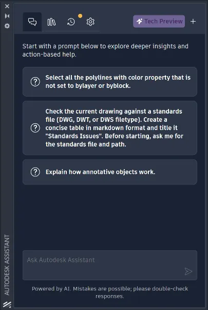
Autodesk Assistant (What's New in 2027)
Autodesk Assistant now offers AI-enhanced chat and prompt-driven workflows. Autodesk Assistant includes the following enhancements:
- Ability to check standards of the current drawing against a standards file
- Selection based on natural language prompt
- Ability to query drawing for information, such as layers list, block usage, etc.
- Prompt library and chat history
Note: These newest Autodesk Assistant enhancements are currently in Tech Preview and will continue to improve over time. Currently, its results may not be accurate.
Close
Forma Data Management Essentials (What's New in 2027)
Forma Data Management Essentials streamlines collaborating with others on your projects. Forma Data Management (formerly Autodesk Docs) helps you organize project files and folders for every stage of your work. Use it to share drawing files, publish sheets, review designs, create transmittals, and track issues. To use Forma Data Management with AutoCAD, make sure to install the latest version of Desktop Connector. To do this, see Install Desktop Connector. This release includes improvements that make it easier than ever to get started with Forma Data Management:
- Forma Data Management Essentials
- Ability to view unsynced projects
- Learning content panel
- Enhanced AutoCAD features in Forma Data Management
Forma Data Management Essentials
AutoCAD and Civil 3D subscriptions now include Forma Data Management Essentials. It provides a central source for project information, helping your team stay connected.
Key features are:
- Online drawing file collaboration
- Permission-controlled access
- File versioning
- File sharing
- File review tools
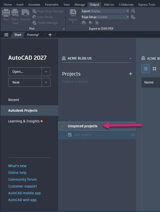
View unsynced projects
You can now see all projects of which you are a member, including those not yet synced. To access files from an unsynced project, use Desktop Connector to sync them to your computer.
Close
Learning content panel
In the Autodesk Projects tab, you'll find a panel with learning resources for Forma Data Management. It includes details about AutoCAD features now enhanced for working with drawings stored in Forma Data Management.
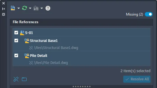
Connected References (What's New in 2027)
Connected References improves the workflow for updating the paths of missing external drawing references (xrefs). When working with drawings that contain references, the new Missing toggle allows you to switch to the Missing References view in the File References pane. This view exclusively shows missing external drawing reference (xref) files.
Close
From the Missing References view, you can perform the following tasks on selected missing references:
- Detach references that are no longer needed
- Update the paths of references by browsing and specifying a new path
- Resolve the paths of references based on suggested paths (applies to drawings opened from an Autodesk project only)
Suggested Path for References
Normally, when a referenced file is renamed or moved, any drawing that depends on it can no longer locate it because its path has changed. As a result, you must update the path for each missing reference to load it properly into AutoCAD. With Connected References and referenced drawing (xref) files stored on Forma Data Management, the External References palette automatically attempts to locate missing reference files that have been renamed or moved. When a missing reference file is found, a suggested path is displayed, which you can accept to avoid manually updating each missing reference.
Changed Commands
EXTERNALREFERENCES - Opens the External References palette.
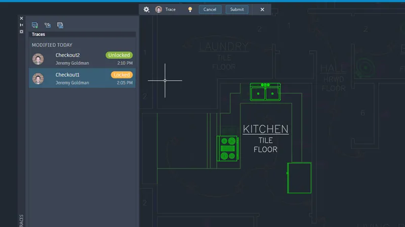
Checkout (What's New in 2027)
Checkout allows a user to edit and propose changes to specific objects in a drawing that someone else has open for editing. Instead of waiting for the drawing to be released by the user who is editing, you can check out the objects you want to edit, edit them in the Trace environment, and then submit your changes for review to the user who has read-write access. The user with read-write access can then merge the changes into the drawing.
Close
Note: Checkout only works with drawings saved in Forma Data Management.
Step 1:One collaborator has a drawing open with read-write access that is saved in Forma Data Management. A second collaborator opens the drawing read-only.
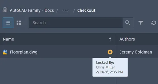
Close
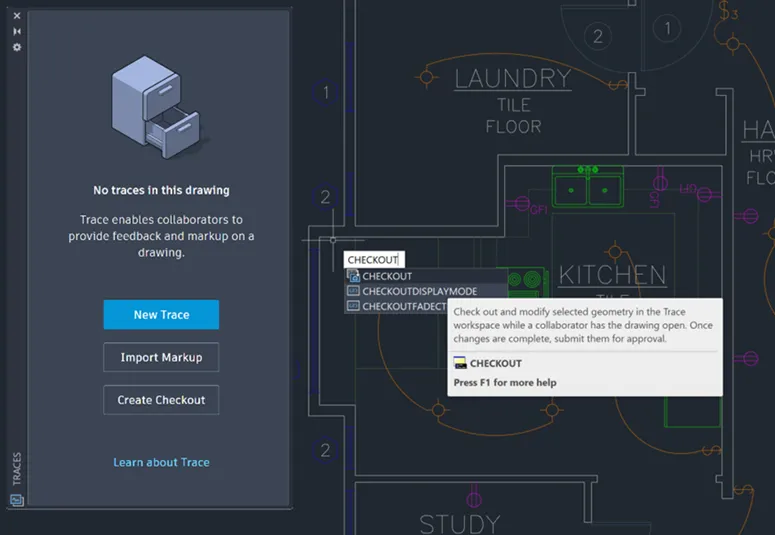
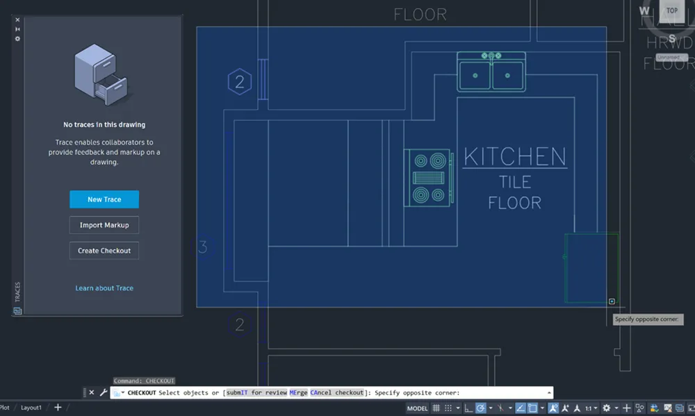
Step 2:The second collaborator starts the CHECKOUT command, then selects and confirms a portion of geometry in the drawing to check out.
Close
The selected portion of the drawing opens in the Trace workspace in a new trace. The checked out geometry locks for the collaborator who has the drawing open with read-write access.
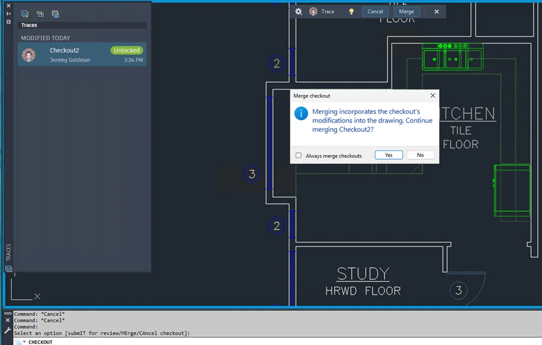
Step 3:The second collaborator makes changes to checked out portion of the drawing in the new trace. When finished editing, they submit and close the trace.
Step 4:The collaborator who has the drawing open with read-write access receives a notification in the drawing that a collaborator has submitted changes. They can then review the changes and decide whether or not to merge them into the drawing.
Close
Object Compatibility in Specialized Toolsets
The following technical considerations apply when using the CHECKOUT command in AutoCAD and its specialized toolsets.
- Checkout filters out custom objects created in AutoCAD specialized toolsets, including AutoCAD Architecture, AutoCAD MEP, AutoCAD Mechanical, AutoCAD Map 3D, and AutoCAD Plant 3D.
- The checkout operation excludes custom toolset objects, and the excluded objects remain unavailable for modification while the drawing is checked out.
- The AutoCAD Electrical toolset does not support Checkout.
New Commands
- CHECKOUT - Check out and modify selected geometry in the Trace workspace while a collaborator has the drawing open. When finished, submit your changes for approval.
New System Variables
- CHECKOUTFADECTL - Controls the amount of fading when TRACEMODE is inactive (TRACEMODE = 0). The setting only applies to objects included in checkouts.
- CHECKOUTDISPLAYMODE - Controls the visibility of checked out objects in the trace and the drawing.
Connected Support Files: Tool Palettes (What's New in 2027)
Tool palette and authoring palette files can be shared with others working on the same Autodesk project stored on Forma Data Management. When configuring an Autodesk project on Forma Data Management, you can specify the locations for the project's tool palette and authoring palette files. For more information on setting up an Autodesk project for use with Connected Support Files, see To Set Up an Autodesk Project to Use Connected Support Files.
Note: Connected Support Files are now available in Forma Data Management and ACC Library.
If you are new to tool palettes and authoring palettes, the following provides a brief description of each:
- Tool palettes: Provide access to project-related blocks, hatch patterns, custom commands, and many other tools that help enforce CAD standards. When loaded, these palettes appear on the Tool Palettes window.
- Authoring palettes: Provide tools for creating and modifying dynamic blocks. When loaded, these palettes appear on the Block Authoring Palettes window within the Block Editor.
Configure Tool Palettes and Authoring Palettes for an Autodesk Project
After Connected Support Files have been set up for an Autodesk project, follow these steps to configure tool palettes and authoring palettes for the project:
Important: Only project members with Project Administrator access can configure Connected Support Files.
1. Upload your project-related tool palette (ATC) files to the Autodesk project.
2. In AutoCAD, open a drawing from the Autodesk project of which you want to configure tool palettes and authoring palettes.
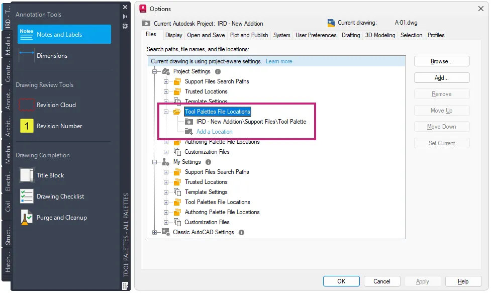
3. In the drawing area, right-click and choose Options.
4. In the Options dialog box, click the Files tab and expand the Project Settings node.
5. Expand Tool Palettes File Locations and then click Add a Location under the node.
6. In the Browse for Folder dialog box, browse to and select the folder containing the uploaded tool palette files, and then click Open.
7. If you uploaded authoring palettes, repeat steps 5 and 6 for the Authoring Palette File Locations setting.
8. Click OK to save the changes.
Close
Display and Use Tool Palettes from an Autodesk Project
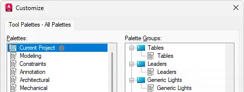
A special tool palette named Current Project is available on the Tool Palettes window and the Customize dialog box. This palette represents the tool palettes loaded from an Autodesk project on Forma Data Management when the project is configured to use Connected Support Files. Use this palette to access project-related tools or to add project-related tool palettes to a tool palette group.
Note: Tool palettes loaded from an Autodesk project are available only when a drawing from that project is open.
Close
Changed Commands
BAUTHORPALETTE - Opens the Block Authoring Palettes window in the Block Editor.
CUSTOMIZE - Customizes tool palettes and tool palette groups.
OPTIONS - Customizes the program settings.
TOOLPALETTES - Opens the Tool Palettes window.
Connected Support Files: Partial Customization (CUIx) Files (What's New in 2027)
Custom user interface (UI) elements can be shared with others and loaded into the AutoCAD desktop app when working on a drawing opened from an Autodesk project on Forma Data Management. When configuring an Autodesk project on Forma Data Management, you can specify which partial customization (CUIx) files that contain custom tools to be automatically loaded when a drawing from that project is opened. As you switch between drawings, any configured CUIx files for an Autodesk project are automatically loaded when their associated drawing is current, and unloaded when a different drawing not associated with that Autodesk project becomes current. For more information on setting up an Autodesk project for use with Connected Support Files, see To Set Up an Autodesk Project to Use Connected Support Files.
Note: Connected Support Files are now available in Forma Data Management and ACC Library.
If you are new to partial customization (CUIx) files, the following resources provide helpful introductions:
- Customization (CUIx) Files
- Customize User Interface (CUI) Editor
- Customizing Ribbon Tabs
- Customizing Ribbon Panels
Creating a Partial CUIx File
Customization (CUIx) files store the definitions of custom command macros and user interface (UI) elements. These UI elements can include ribbon tabs, ribbon panels, toolbars, and more. Before you create custom command macros or UI elements, you must first create a CUIx file. Follow these steps to create a partial CUIx file that can be loaded with other CUIx files:
- Click Manage tab Customization panel User Interface.
- In the Customize User Interface (CUI) Editor, click the Transfer tab.
- In the right pane, click Create a New Customization File.
- In the Save As dialog box, browse to the location where you want to save the new CUIx file.
- In the ✅File Name text box, enter a ✅File Name and click Save.
After creating the CUIx file, you must load it into the Customize User Interface (CUI) Editor to define the custom command macros and UI elements you want to make available when a drawing file from an Autodesk project is opened.
Loading and Editing a Partial CUIx File
Follow these steps to load and edit a partial CUIx file in the CUI Editor:
1. In the Customize User Interface (CUI) Editor, click the Customize tab.
2. In the Customizations In pane, click Load Partial Customization File.
3. In the Open dialog box, browse to and select the CUIx file to load and click Open.
4. In the Customizations In pane, click the Loaded CUI file drop-down list and select All Customization Files.
5. Scroll down and expand the Partial Customization Files node.
6. Expand the node for the CUIx file that you loaded in Step 3.
7. Create new command macros in the Command List pane and add new UI elements that reference your custom command macros under the appropriate nodes.
8. Click Apply to save the changes.
9. After adding the new UI elements and saving the changes, right-click the CUIx file under Partial Customization Files and choose Unload.
10. Click OK to close the CUI Editor.
Adding a Partial Customization (CUIx) File to an Autodesk Project's Settings
After setting up Connected Support Files for an Autodesk project and creating a CUIx file, follow these steps to configure your partial customization (CUIx) files for a project:
Important: Only project members with Project Administrator access can configure Connected Support Files.
1. Upload your project-related partial customization (CUIx) files to the Autodesk project.
2. In AutoCAD, open a drawing from the Autodesk project of which you want to configure tool palettes and authoring palettes.
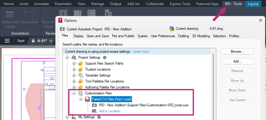
3. In the drawing area, right-click and choose Options.
4. In the Options dialog box, click the Files tab and expand the Project Settings node.
5. Expand Customization Files Partial CUI Files (Auto Load) and then click Add a Location under the node.
6. In the Browse for Folder dialog box, browse to and select the CUIx file you want to load when a drawing from the Autodesk project is opened and set current. Then click Open.
7. Note: When selecting a CUIx file to load with the Autodesk project, make sure to not select the product's main customization file.
8. If you uploaded multiple CUIx files, repeat steps 5 and 6 for each file.
9. Click OK to save the changes.
Close
Changed Commands
CUI - Manages the customized user interface elements in the product.
OPTIONS - Customizes the program settings.
Quality improvements
Content Library:The faulty content library proxy element no longer causes crashes.
Downgrade Save:The drawing file version is preserved when saving to the AutoCAD 2000 or AutoCAD LT 2000 format.
Reference Edit:In-place editing of external references that contain symbols no longer causes crashes.
Open and Close:Opening and closing a drawing that contains a DGN underlay no longer causes crashes.
AMSHIDE Command:The Hide Situation dialog box retains its initial size when the command is canceled.
AMSCRIPT Command:Title block exchange is now completed successfully using the AMSCRIPT command.
AMSECTIONLINE Command:You can now snap to points on the section line when copying or moving it.
2D Structure
- Downgrading a drawing to an older format, such as AutoCAD Mechanical 2007, no longer causes crashes.
- Parts count is no longer affected when using the UNDO command.
Parts List Filters
- Saving the drawing no longer results in errors after creating a new balloon using the Manual Placement option.
- The custom parts list is now updated whenever a new part is inserted into the drawing.
Performance
- The dot small blank arrowhead no longer produces errors during copy, clip, or save operations.
- Editing the overall dimension scale property no longer produces errors.
Open and Save/Save As: When a drawing is opened in AutoCAD Mechanical 2027, the command line displays the AutoCAD Mechanical file format in which the drawing was last saved.
Additional enhancements and changes
Layout Tab Switching Performance:Improvements were made to reduce the amount of time it takes to switch layout tabs.
3D Graphics System Enhancements:The 3D graphics system (GSF), controlled by the FASTSHADEDMODE system variable, now provides a more stable and efficient experience. These updates improve visual fidelity by better supporting large coordinates, occluded edges, materials, lights, textures, shadows, sky, and backgrounds. Additionally, the Realistic (Fast) visual style is now on by default.
Removal of Support for AutoCAD Web & Mobile:The Open From Web & Mobile (OPENFROMWEBMOBILE) and Save To Web & Mobile (SAVETOWEBMOBILE) features have been removed from this release. If you previously saved your drawing files to AutoCAD Web & Mobile, it's recommended to utilize Forma Data Management to store and access drawing files anywhere.
Removal of Shared Views:The Shared Views feature has been removed from this release. If you previously used Shared Views, it's recommended to utilize Forma Data Management to store and share drawing files with others.
Push to Forma Data Management Replaces Push to Autodesk Docs:The Push to Autodesk Docs feature has been updated to Push to Forma Data Management. New commands and system variables were introduced to display and close the Push to Forma Data Management palette.
Removal of Support for the MrSID Image Format:Image files saved in the MrSid format can no longer be attached to a drawing file. MrSID images will need to be saved to a supported file format and reattached.
Removal of Support to Create a PostScript File:The PSOUT command has been removed in this release and the EXPORT command no longer supports the ability to export to the format. If you need to create a PostScript file from a drawing, configure a PC3 file according to the output needed.
Autodesk AutoCADis computer-aided design software that allows you to efficiently create and document 2D and 3D designs. Industry-specific Autodesk tools, such as architecture, plant 3D, map 3D, MEP, electrical, mechanical and grid design, make Autodesk AutoCAD the number one software for architects, engineers and construction professionals.
TheMechanical toolset, included as part of the AutoCAD including specialized toolsets offering, can help save many hours of design and rework by automating many common tasks. With the Mechanical toolset, you can: Access the library of standards-based parts, tools, and custom content; customize properties of object types and create them on custom layers; automate tasks such as creating bills of materials (BOMs).
AutoCAD Mechanical Modeling Tutorials
These collection of videos are meant for those who are interested in Mechanical modeling and visualization using AutoCAD 3D .
Autodeskhelps people imagine, design and create a better world. Everyone-from design professionals, engineers and architects to digital artists, students and hobbyists-uses Autodesk software to unlock their creativity and solve important challenges.
Owner:Autodesk Inc.
Product Name:AutoCAD Mechanical Toolset
Version:2027.0 with LPs & Offline Help
Supported Architectures:x64
Website Home Page :
www.autodesk.com
Languages Supported:multilanguage
System Requirements:Windows *
Size:9.5 Gb

Buy Premium From My Links To Get Resumable Support,Max Speed & Support Me
KatFile
gvjck.Autodesk-AutoCAD-Mechanical-2027-with-LPs-Offline-Helps.part1.rar.html
gvjck.Autodesk-AutoCAD-Mechanical-2027-with-LPs-Offline-Helps.part2.rar.html
Rapidgator
AutodeskAutoCADMechanical2027withLPsOfflineHelps.html
DDownload
gvjck.Autodesk-AutoCAD-Mechanical-2027-with-LPs-Offline-Helps.part1.rar
gvjck.Autodesk-AutoCAD-Mechanical-2027-with-LPs-Offline-Helps.part2.rar
FreeDL
gvjck.Autodesk-AutoCAD-Mechanical-2027-with-LPs-Offline-Helps.part1.rar.html
gvjck.Autodesk-AutoCAD-Mechanical-2027-with-LPs-Offline-Helps.part2.rar.html
Links are Interchangeable - No Password - Single Extraction